Organize constructions into a project
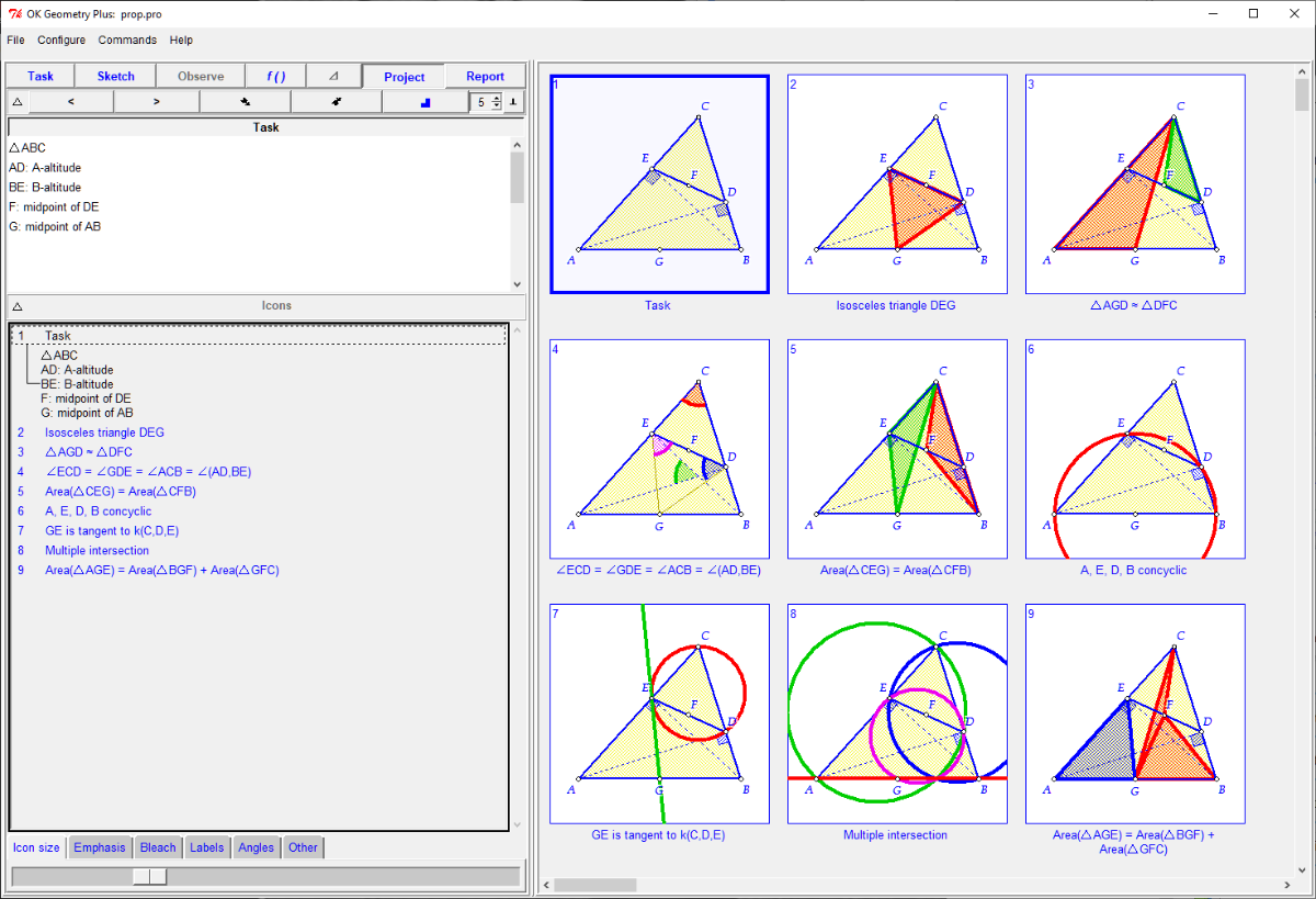
If we want to visualise and consider several related configurations at the same time, we can organise them together with the corresponding textual comments in a project. When a dynamic construction is included in a project, it takes the form of an icon. Icons can be placed on the display in different ways. From any icon in a project the underlying construction and comments can be accessed and edited at any time. In a way, constructions and projects are analogous to files and directories (in fact, icons can also represent also sub-projects of a project).Projects can be seen as a container, in which the contained constructions can be visualised at once. But they can also be more than that, if we give them appropriate content. For example, a project can also be a selection of the properties of a configuration observed by OK Geometry. In fact, an observed property of a construction can be placed directly on a project. The figure below shows the visual aspect of such a project: the first icon shows a geometric construction, the other icons visualise some observed properties of this construction.

aThe content of a project can be saved in various forms and different printable formats.
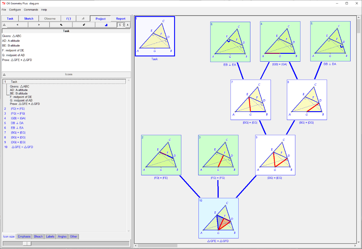
The icons with selected properties of a construction can be arranged spatially to show the scheme of a proof for a considered assertion. This is the case with the project visualised below. The green icons stand for the givens, the blue for the assertion to be proven and the white for the observed and deduced facts used in the proof.

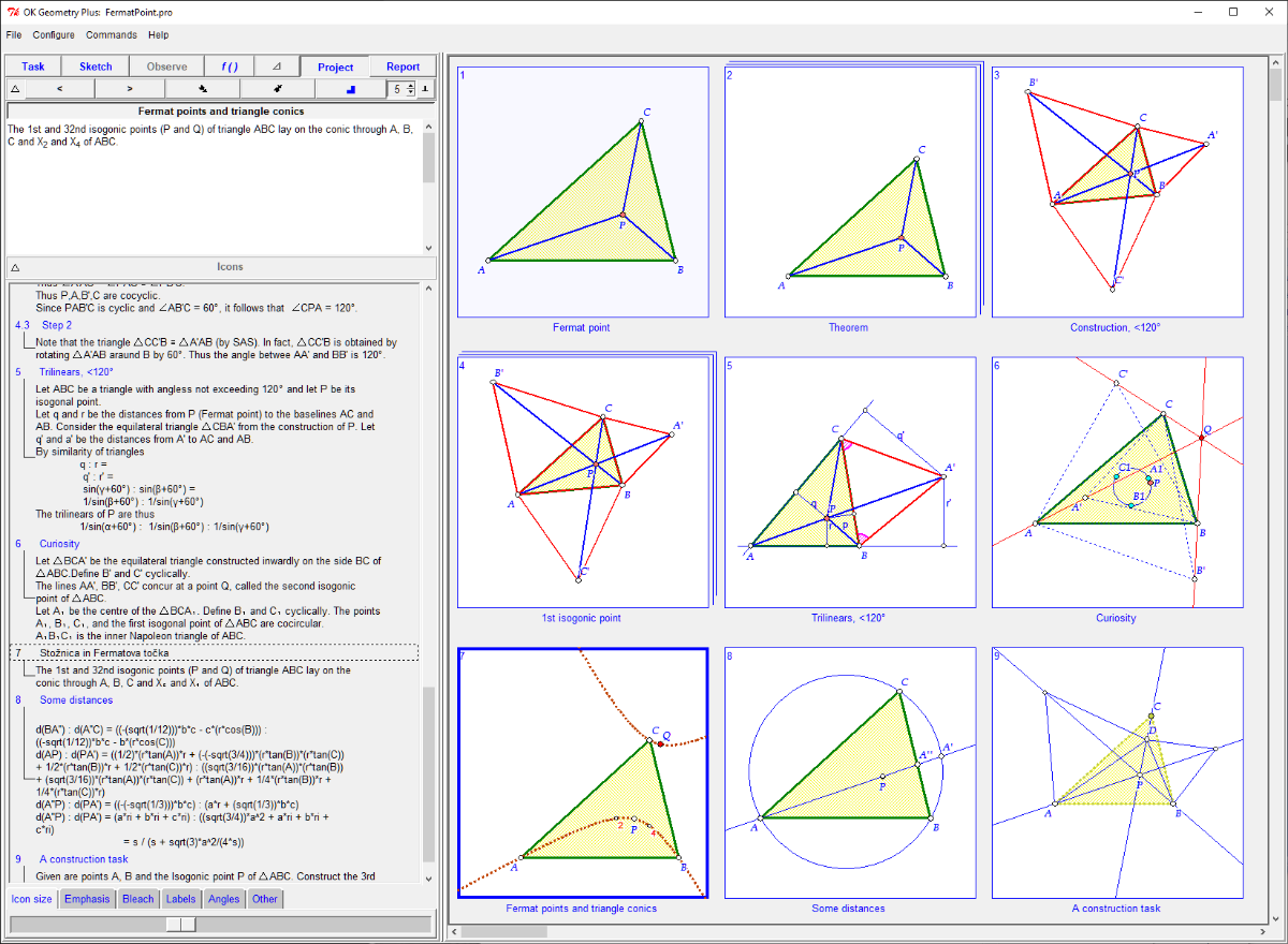
In a project you can also collect facts (illustrations, constructions, theorems, proofs, etc.) on a geometry topic. Such projects function like a geometric memo or a geometry notebook. For example, the project shown below is about the Fermat point of a triangle. You will notice that the second icon in the first row is a sub-project of the main project.
